Arc flash is a sudden, explosive release of energy from an...
ReadMotor starting: understand, quantify and mitigate
Voltage sags are a common issue during electrical motor starting and could be particularly dramatic in weak or islanded power systems, like the ones found in industrial settings, drilling rigs, and offshore platforms, and they can lead to equipment damage and even system-wide interruptions. In this article we will explore the nature of this phenomenon and why it happens, using a practical example. We will also examine why it is crucial to use reduced voltage motor starters, the most common types of starters available, and their drawbacks.
Understanding motor-starting induced voltage sags.
Within the context of this article, a voltage sag occurs when an electric motor, typically of the induction or asynchronous type, draws a large amount of current from the power source to which it is connected for starting purposes. Within the same order of magnitude, the current could be a few times the nominal of the motor. The most drastic case is when the connection of the motor occurs “across the line”, i.e.: the windings of the motor are connected directly and suddenly to the voltage source, with no voltage reduction means. Depending on many factors, the event could last a few hundred power cycles, but could extend to seconds.
During the immediate cycles after connection, the overcurrent happens because the rotating magnetic fields and torque within the motor must overcome the inertia of the motor itself, and the inertia of its mechanical load, which are all fully stopped by the time the connection occurs. In practicality, this would be the same as connecting the motor to a power source while its rotor is locked, so the motor demands its “locked rotor current” or “locked rotor amperes” (LRA, as commonly found in the specialized literature and some motor nameplates with NEMA letter codifications).
This can also be visualized using the typical simplified induction motor model, which is shown in Figure 1. With “S” representing the slippage of the motor versus the rotation speed of the magnetic field (submultiples of 377 radians per second in 60Hz systems), a locked rotor situation implies S = 1, which then makes the equivalent resistance of the rotor (R_rotor/S) to become its minimum possible value, drawing the maximum possible current from the source.
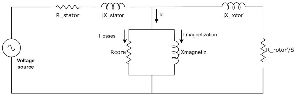
After the inertia of the rotating masses is defeated and start to move, the overcurrent is consequence of the dynamic performance of the motor, which typically demands a significant amount of current when rotating at speeds too far from the nominal. This can also be visualized with the aid of Figure 1:
- If the motor rotates at speeds too far from the nominal à “S” tends to 1 à “R_rotor/S” tends to its minimum possible value à currents are bigger.
- If the motor rotates at speeds close to the nominal à “S” tends to 0 à R_rotor/S” tends to its maximum possible value à currents are smaller.
Assuming for a moment the voltage source is unaffected by the start, if the motor torque is greater than the opposing torque of the mechanical load being driven (a compressor, pump, fan, conveyor, etc.), over the whole spectrum of speed, then there will be a net accelerating torque that would allow the completion of the start. This case can be appreciated in Figure 2, which shows examples of typical torque versus speed curves of an electric motor and a mechanical load, the latter corresponding to the one of a centrifugal pump.
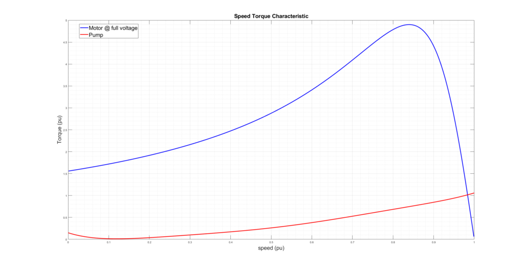
If at any point of the torque / speed curves the motor line becomes less than the load line, then the starting process will cease, and the rotating speed of the masses would settle at the intersection point of the curves. If this interception happens at other than the intended operating speed, the starting process is said to be stalled or failed, which could lead to motor overheating due to overcurrent, overload trips, sustained voltage sags, among others. The case shown in Figure 2 corresponds to a successful start, in which the interception of curves happens in the vicinity of the synchronous speed and nominal torque.
In a real life, non-ideal case, the voltage source in Figure 1 would be diminished by the overcurrent drawn during the start process. This is the voltage sag that occurs in every “across the line” motor start, and its severity depends in big part on the “strength” of the source (the total impedance seen by the motor in the direction of the source), in relationship to the size of the motor (the bigger the motor, the more severe). Such voltage decrease will in turn reduce the elevation of the motor’s torque curve shown in Figure 2. If substantial enough, the torque of the motor could become less than the one of the pumps long before reaching nominal speed, which then will result in a stall or failed start.
Quantifying motor-starting induced voltage sags.
As indicated before, the two main factors determining the severity of voltage sags due to motor starting are the strength of the source and its relationship with the size of the motor. As this case-by-case situation warrants an equal case-by-case analysis, we will use the example case of Figure 3 to illustrate about quantification.
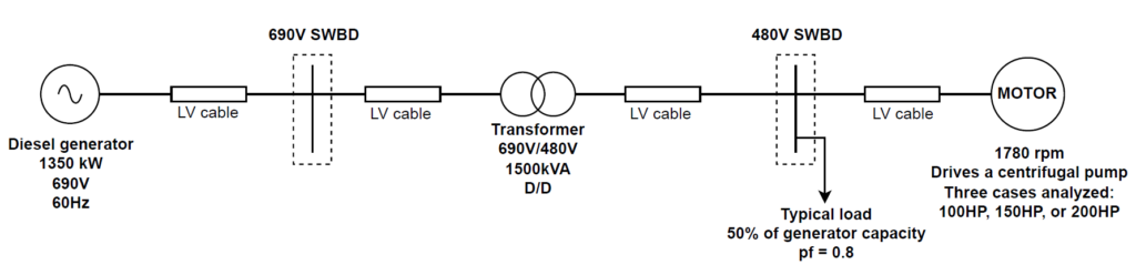
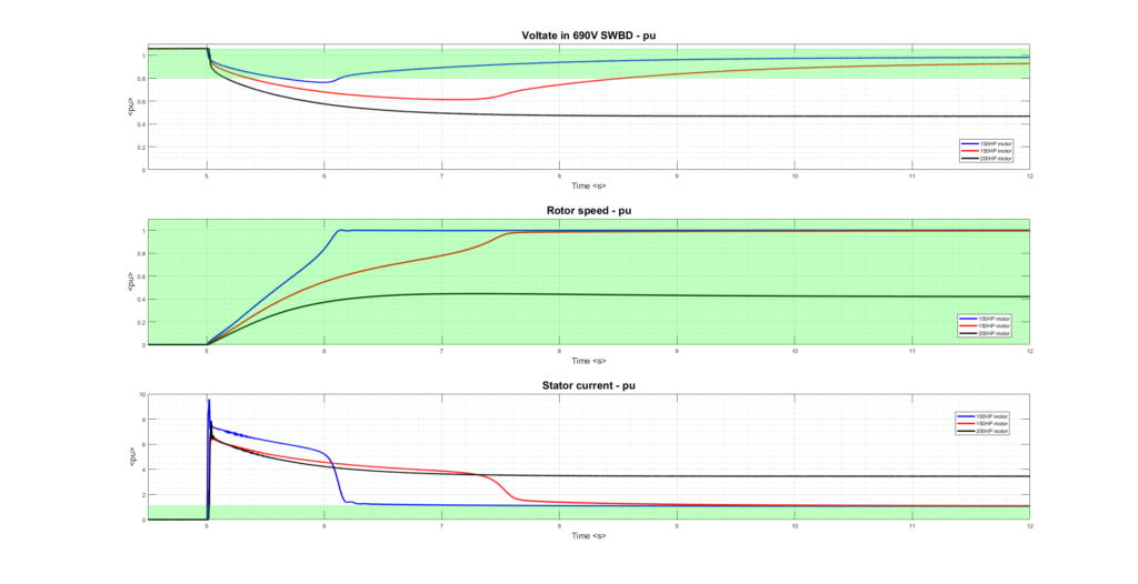
Figure 3 corresponds to a typical industrial or oil and gas, islanded and “weak” power system. The system includes a 1350 kW generator at 690V, with standard speed governor and excitation control systems, providing power to an electric motor via a series of typical low voltage cables and transformers. A typical other-than-motor load is also present. Three across the line motor start cases were simulated in Matlab/Simulink, for three different sizes of motors: 100HP, 150HP and 200HP. In all cases, the motors are assumed to be driving a centrifugal pump, with torque versus speed characteristics like the one shown in Figure 2. It must be noticed that this case corresponds to an academic-like illustration, as hardly ever one single engine is used in industrial or oil and gas settings (typically at least 2 are on-line).
The results of the simulated motor starting events are shown in Figure 4, where normally acceptable ranges are indicated with green shaded areas, suggest that even a typically sized motor of 100HP would depress the voltage in the main switchboard of the system beyond a normally used threshold of 20%, for transient variations due to step load changes. Moreover, bigger size motors of 150HP and 200HP would extend the starting process beyond 3 seconds, with the 200HP motor stalling and producing, under the assumption that protection systems were not in place, permanent undervoltage, permanent over current, and unsuccessful start (the load never reaching its intended speed).
Mitigating motor-starting induced voltage sags.
Several methods do exist to mitigate this undesired power system behavior, and they all operate under the principle of “reduced voltage” provided to the motor during the start process. Among them, the most popular ones, with their pros and cons, are:
- Star-Delta Starters: by initially connecting the motor windings in star configuration, the starting current is typically reduced to one-third of that which would flow if the motor were started in delta.
- Pros:
- Simple and Reliable: Star-delta starters are simple in design and have been proven reliable over many years of use.
- Cost-Effective: They are generally cheaper than other types of reduced voltage starters.
- Ease of Installation: Star-delta starters require less complex wiring compared to more sophisticated starters.
- Cons:
- Limited Starting Torque: The starting torque is also reduced to one-third that available at a delta connection, which might not be suitable for heavy-load starts.
- Voltage Dip: Still causes a significant voltage dip upon starting, which can affect other equipment.
- Complexity in Control: Requires additional controls to switch from star to delta after the motor reaches a certain speed.
- Not Suitable for High-Inertia Loads: May not be suitable for applications where the load has a high inertia or requires a high starting torque.
- Pros:
- Soft, or Power Electronics-based Starters: use solid state devices to achieve granular control of voltage and/or frequency over the motor
- Pros:
- Adjustable Starting Conditions: Soft starters allow for adjustable starting and stopping parameters, providing smooth acceleration and deceleration.
- Reduced Mechanical Stress: Limits mechanical stress on the motor and the driven equipment during starting.
- Reduced Electrical Stress: Reduces electrical stress on the power distribution network due to controlled starting current.
- Cons:
- Cost: Generally, more expensive than traditional starters like star-delta.
- Complexity: More complex circuitry and components that may require additional maintenance and have a higher chance of failure.
- Heat Generation: May require additional cooling or ventilation as they can generate heat during operation.
- Pros:
- Auto-transformers: Offers reduction in starting current by temporarily reducing voltage to the motor.
- Pros:
- Adjustable Starting Torque: Allows for adjustable starting torque to suit specific application requirements.
- Versatility: Can be used for a variety of applications and motor sizes.
- Cons:
- Costly: More expensive than direct-on-line or star-delta starters.
- Size and Weight: Can be large and heavy, requiring more space for installation.
- Maintenance: More moving parts (e.g., tap changers) can result in higher maintenance requirements.
- Pros:
- Primary Resistance: limits the starting currents of the motor by interposing resistors in the stator windings during start.
- Pros:
- Simple Concept: Uses resistors to drop voltage and is a conceptually simple method of starting.
- Applicability: Suitable for both wound-rotor and squirrel-cage induction motors.
- Cons:
- Wasted Energy: The energy is wasted in the resistors as heat during the start, making it less efficient.
- Maintenance: The resistors and associated switching gear may require regular maintenance.
- Cost of Resistors: Depending on the size of the motor, the resistors can be costly.
- Pros:
Key takeaways.
Effectively managing the challenges of motor starting and mitigating the associated voltage sags is crucial for maintaining the stability and efficiency of power systems, particularly in environments with weak or isolated systems. The selection of the appropriate motor starter is pivotal in striking the right balance between technical requirements and economic considerations.
At Altus Dexter, we possess the expertise to navigate these complex decisions, providing tailored solutions that consider both the unique operational demands and the intricate electrical characteristics of our clients’ systems. Our competence in addressing voltage sag issues and motor starting challenges is backed by robust analysis, cutting-edge simulation tools, and a deep understanding of both traditional and innovative starting methods.
With a track record of success in diverse industrial sectors, Altus Dexter stands as your capable and qualified partner in ensuring that your motor starting operations are efficient, reliable, and optimized for your specific needs. Engage with us to safeguard your operations against voltage sags and to ensure seamless, uninterrupted productivity.
Recommended citation.
Pineda, F., “Motor starting: understand, quantify, and mitigate”. Website article (2023). Altus Dexter. www.altusdexter.com
References.
[1] Vittal, Ayyanar, “Grid Integration and Dynamic Impact of Wind Energy”, Springer; 1st edition, 2013.

About the author
Fabian Pineda, P.E., is the Founder and Managing Director of Altus Dexter. He has extensive experience in project management, design, operation, reliability, and maintenance of electrical systems for industrial, oil, gas and offshore applications.
We also recommend
Electrical Reliability in Oil and Gas: A Study Case
In the high-stakes environment of oil and gas, electrical system reliability...
ReadCONTACT US
Get in touch with us. We offer complimentary consultations to our prospective clients. Feel free to fill out the form, call us or send us an e-mail.
- (832) 773-1194
- info@altusdexter.com